The HomeScope can be controlled by physical interaction with hardware located directly on the microscope or by software accessing the computer GPIOs. Applications running on the Raspberry Pi can access them via the gpio utility.
Direct user interaction
The user can communicate directly with the Arduinos; via a Joystick forXY movements and via two push-down buttons for Z movement. The user can also adjust the light level by controlling the voltage provided to the LED light directly via a potentiometer. Notice that image and video captured can only be done from a computer since the microscope only has a camera to see the sample.
Computer control with Gtk and gpio
Using GPIOs and a six-bit message protocol the Raspberry Pi can transmit information to the Arduinos so we can control the HomeScope from the Linux computer by using gpio, raspivid, and raspistill directlyfrom the Linux shell. Although in previous guides we focused on shell scripting for timelapses, in this guide we explore the power of the Gtk GUIs and the Linux API have when developing algorithms for open microscopy. It is in this sense that this guide is more of a hacker guide centered around writing software to control open hardware based microscopes.
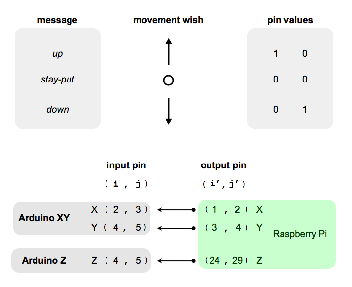
The code running on the Arduinos provide the Raspberry Pi with a rudimentary messaging protocol to communicate movement wishes to the motors so they would move in some of the allowed directions. It consist of a two-bit word per degree of freedom meant to communicate the movement the Raspberry Pi wishes via it GPIOs. Using two output pins (i’, j’) for each of the three degrees of freedom X,Y,Z, we need six output pins on the Pi side (1, 2, 3, 4, 24, 29). We show here in the figure above such a simple messaging protocol. The Raspberry Pi can talk to Arduino XY (via a Logic converter) using four input pins (2, 3, 4, 5) on the Arduino XY side coding messages for two degrees of freedom (XY). Similarly the Raspberry Pi can talk to the Arduino Z using two input pins (4, 5) on the Arduino Z side to transmit messages and control focus (Z). Each degree of movement freedom has the following structure of pin states: (0,0) stationary state, communicate the stay-put message telling the Arduinos to stay in the current position; (1,0) move up, telling the Arduinos to increase the current microscope position; and (0,1) move down, telling the Arduinos to decrease the current position.
The Raspberry Pi can monitor if the Arduino (both XY and Z) is in the listening or actuating state by monitoring a pin on the Pi side which reflects the Arduino’s signal_pin state. We use PIN 12 on the Arduinos to send this one-bit message to the Raspberry Pi. Currently however, the code on the Pi ignores this information.
Using the gpio utility provided by the WiringPilibrary together with the Gtk library we build a couple of GUI based applications to control the HomeScope from a Linux based computer. Two pieces of code written in the C language are used to produce the Apps needed to control the microscope: OpenScope and OpenStage.