The OpenStage is the application controlling the XY movements of the HomeScope. It is also written in C, and also uses Gtk and it is made from the following five files:
 open_stage.c
- build_XY.ui
- kimero_LAB.tiff
- compass_rose.tiff
- open_stage_view_area.jpg
As before, the code file open_stage.c implements the message protocol so the Raspberry Pi can talk to Arduino XY via Arduino input pins PIN 2, PIN 3 for the X messages and PIN 4, PIN 5 for Y messages. These messages consists of to two two-bit words (one for each of the two degrees of freedom), corresponding to messages: (00), stay-put; (10), up; (01), down. On the Raspberry Pi side; we set the communication output PIN 1 and PIN 2 for X messages, and PIN 3 and PIN 4 for Y messages. In the C code, we set these pins using the Linux system call and the gpio utility from WiringPi. That way we set the four Raspberry pins PIN 1, PIN 2, PIN 3, PIN 4; all to a LOW. The GUI translate Gtk button event signals to a couple of two-bit words coordinating the stage movements.
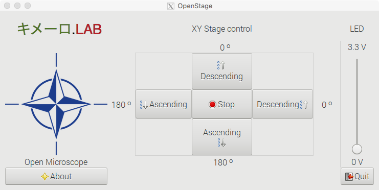
Again, as before, we use Glade as graphical development environment and within the C code, we call GtkBuilder to extract all the data needed from the file builder_XY.ui which contains all the XML code needed to generate all the GUI’s Gtk Objects. Just as before the kimero_LAB.tiff and compass_rose.tiff files correspond to our lab logo and and an application image icon. The file open_stage_view_area.jpg correspond to the image used to display the coordinates of the scanning area. It is shown when calling the About dialog.
As with the other application, we start by including two needed libraries: the Gtk and stdlib
#include <gtk/gtk.h>
#include <stdlib.h>
We define the function set_gpio_modesto set up the default pin values and structure
void set_gpio_modes(void)
{
// set pins to 00,00 state meaning no movement
system("gpio mode 1 OUT");
system("gpio write 1 0");
system("gpio mode 2 OUT");
system("gpio write 2 0");
system("gpio mode 3 OUT");
system("gpio write 3 0");
system("gpio mode 4 OUT");
system("gpio write 4 0");
//set the PWM pin and set it to zero
system("gpio mode 23 pwm");
system("gpio pwm 23 0");
}
This App controls the HomeScope illumination system; this corresponds to a single white LED placed under the Stage and aimed at the sample. Computer regulation of the light intensity is accomplished by linking a Gtk scale bar on the GUI to the PWM PIN 23 of the Raspberry Pi to power the LED with a variable voltage; ranging from zero to 3.3V. Thus, we define a handler pwm_scale_moved which responds to a user sliding the Gtk scale on the GUI; this triggers gpio to write a new value to the PWM pin via system call.
static void pwm_scale_moved (GtkRange *range, gpointer user_data)
{
gdouble pos = gtk_range_get_value(GTK_RANGE(range));
gint pwm_value;
pwm_value = (gint) pos;
gchar *str = g_strdup_printf("gpio pwm 23 %d", pwm_value);
system(str);
}
Now we need to link the four Gtk button objects on the GUI that we use for each of the movement directions available. We also need to code a stop button, and all the event handlers. These five handlers then generate and transmit the messages from the Raspberry Pi to the Arduino XY so it can actuate them. The first one of these handlers, move_x_up, handles “up” movements on the X axis by sending a (1,0) message from output PINS 1 and 2 on the Raspberry Pi side .
static void move_x_up (GtkWidget *widget, gpointer data)
{
g_print("Hello x axis: we are going up!\n");
system("gpio write 1 1");
system("gpio write 2 0");
}
Similarly, for handling “down” movements on the same axis with define the function move_x_down. This handler sends the (0,1) message from output PINS 1 and 2 on the Raspberry Pi side.
static void move_x_down (GtkWidget *widget, gpointer data)
{
g_print("Hello x axis: we are going down!\n");
system("gpio write 1 0");
system("gpio write 2 1");
}
For the analogous pair of movements on the Y axis; we move “up” with move_y_up which sends a (1,0) message from output PINS 3 and 4 on the Raspberry Pi side.
static void move_y_up (GtkWidget *widget, gpointer data)
{
g_print("Hello y axis: we are going up!\n");
system("gpio write 3 1");
system("gpio write 4 0");
}
Moving “down” is accomplished with the functionmove_y_down which sends a (0,1) message from output PINS 3 and 4 on the Raspberry Pi side.
static void move_y_down (GtkWidget *widget, gpointer data)
{
g_print ("Hello y axis: we are going down!\n");
system("gpio write 3 0");
system("gpio write 4 1");
}
To instruct the Arduinos to stop moving all together we define handler stop_moving, which generates and transmit a (0,0) message to all relevant output PINS (1, 2, 3, 4) on the Raspberry Pi side.
static void stop_moving (GtkWidget *widget, gpointer data)
{
g_print ("Stop moving stage now!\n");
system("gpio write 1 0");
system("gpio write 2 0");
system("gpio write 3 0");
system("gpio write 4 0");
}
As before, we also define a Gtk about dialog box to inform for the curious user with handler show_about.
// HERE GOES THE ABOUT DIALOG BOX For info
static void show_about(GtkWidget *widget, gpointer data)
{
GdkPixbuf *pixbuf = gdk_pixbuf_new_from_file("open_stage_view_area.jpg", NULL);
GtkWidget *dialog = gtk_about_dialog_new();
gtk_about_dialog_set_program_name (GTK_ABOUT_DIALOG(dialog),
                                   "OpenStage Controller");
gtk_about_dialog_set_version(GTK_ABOUT_DIALOG(dialog), "version 1, October 2017");
gtk_about_dialog_set_copyright(GTK_ABOUT_DIALOG(dialog),"Open source Code, The Keymer Lab");
gtk_about_dialog_set_comments(GTK_ABOUT_DIALOG(dialog),
                          "The Open Stage, a GUI mapping Gtk buttons
                           into Arduino micro-servo degrees.
                           Thanks to Fondecyt 1150430.");
gtk_about_dialog_set_website(GTK_ABOUT_DIALOG(dialog),
                           "http://keymerlab.nl");
gtk_about_dialog_set_logo(GTK_ABOUT_DIALOG(dialog), pixbuf);
g_object_unref(pixbuf), pixbuf = NULL;
gtk_dialog_run(GTK_DIALOG (dialog));
gtk_widget_destroy(dialog);
}
Like in the previous application (OpenScope), clicking on the About button of the OpenStage brings up a Gtk dialog window with basic information about the application. For the case of the OpenStage, clicking on the About button shows the image stored in the file open_stage_view_area.jpg. It displays the coordinates of the spatial scanning area in both; linear mm and servo degrees. In this image, we can see a gray area with a red dot at the middle. Such red dot is at servo coordinates (90,90) corresponding to the middle of the servo’s range. The view area is smaller and it is depicted here as a small white square. The size of this area depends on the magnification of the objectives used. OpenStage translates the scanning area leaving the optical and illumination systems stationary centered at the red dot corresponding to their axis of alignment with the viewing area.
As with any application written in C, the main function main implements the main section of the code as well as it glues together all the functions defined above.
int main (int argc, char *argv[])
{
GtkBuilder *builder;

GObject *window;
GObject *button;
GObject *scale;

gtk_init (&argc, &argv);

/* Construct a GtkBuilder instance and load our UI description */
builder = gtk_builder_new ();
gtk_builder_add_from_file (builder, "builder_XY.ui", NULL);

/* Connect signal handlers to the constructed widgets. */
window = gtk_builder_get_object (builder, "window");
g_signal_connect (window, "destroy", G_CALLBACK (gtk_main_quit), NULL);

button = gtk_builder_get_object(builder, "stop_button");
g_signal_connect (button, "clicked", G_CALLBACK(stop_moving), NULL);

button = gtk_builder_get_object(builder, "x_up_button");
g_signal_connect (button, "clicked", G_CALLBACK(move_x_up), NULL);

button = gtk_builder_get_object(builder, "x_down_button");
g_signal_connect(button, "clicked", G_CALLBACK(move_x_down), NULL);

button = gtk_builder_get_object(builder, "y_up_button");
g_signal_connect (button, "clicked", G_CALLBACK(move_y_up), NULL);

button = gtk_builder_get_object(builder, "y_down_button");
g_signal_connect(button, "clicked", G_CALLBACK(move_y_down), NULL);

button = gtk_builder_get_object(builder, "about_button");
g_signal_connect(button,"clicked",G_CALLBACK(show_about),GTK_WINDOW(window));

button = gtk_builder_get_object (builder, "quit_button");
g_signal_connect(button, "clicked", G_CALLBACK (gtk_main_quit), NULL);

scale = gtk_builder_get_object (builder, "pwm_scale");
g_signal_connect(scale, "value-changed", G_CALLBACK (pwm_scale_moved),NULL);

set_gpio_modes();
gtk_main ();
return 0;
}